BG Motor has been a DC motor manufacturer and AC motor supplier for 30+ years.


DC brushless motor driver manufacture
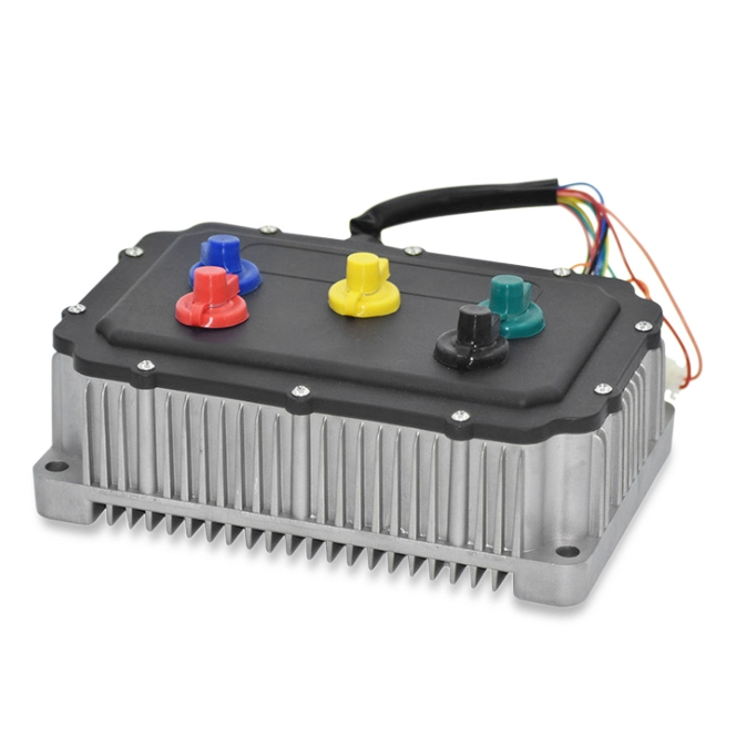
Model Number:ZM-BL 4810F Brushless Motor Drive
Output current: 8A
Range of Voltage:12-32VDC
Range of Rated Speed: 3000-20000rpm
Size:/
Lifespan:/
Electrical performance indicators
Electrical performance (ambient temperature Tj=25℃)
|
Power supply |
D C 18V ~50 V DC |
|
Rated current |
A not greater than 10 |
|
Rated power |
A maximum of 480 W (No motor with excessive power) |
|
Insulation resistance |
﹥500 MΩ at room temperature |
|
Insulation strength |
0.5 KV ,1 min at room temperature and atmospheric pressure |
Use of environmental parameters:
|
Cooling mode |
|
Natural air cooling (forced air cooling is recommended) |
|
Use of environment |
Events |
Avoid dust, oil mist and corrosive gases |
|
|
Temperature |
0℃~+50℃ |
|
|
Humidity |
﹤80% RH, no condensation, no frosting |
|
|
Vibration |
﹤0.5 G (4.9 m/s) 2)10 Hz-60Hz( Discontinuous operation) |
|
Preservation temperature |
|
-20℃~+65℃ |
|
Shape dimensions |
|
118×75.5×34 mm |
|
Weight |
|
About 0.3 Kg |
[Note that] due to severe changes in the ambient temperature of storage and transportation, condensation or frosting is easy to occur. The driver should be placed for more than 12 hours until the temperature of the driver is consistent with the ambient temperature.
Port Description
| Function | dentification | Note |
| Indicator | POWER | The green power indicator indicates that the power supply is normal. |
| ALARM | red status indicator light, slow flash wait, flash run and change with motor speed; normally lit as faulty or offline. |
|
| RS232 communication ports | TTL | Can be external speed display board, display speed; can also be connected to the computer, used to set the driver parameters. See Debugging Software Description |
| Control signal terminal | +5V1 | Control Signal Power Supply (Built-in Power Output) |
| VSP | External Speed Control Signal The control mode :1, through the external potentiometer to change the VSP terminal voltage to achieve 0~100% speed adjustment, range 0~5 V;. 2.PWM speed regulation: PWM positive terminal VSP, negative terminal GND1, by changing the duty cycle of input frequency to achieve speed regulation, the range of 10~300 Hz.. |
|
| FG | Motor speed pulse output, can be measured by the frequency of this signal, and then converted to the actual speed of the motor |
|
| DIR | The high and low level controls the motor forward and reverse, GND1 motor reverse (counterclockwise), no GND 1 or +5 motor forward (clockwise). |
|
| EN | Motor enable control, EN connected GND1, motor turn (on-line state), EN not connected or high level, motor do not turn (off-line state, this state red light always on) |
|
| GND1 | Control Signal Power | |
| Hall Letter End | +5V2 | motor hall power supply positive. |
| H U | Hall sensor signal U phase input. | |
| HV | Hall sensor signal V phase input. | |
| H W | Hall sensor signal W phase input. | |
| GND2 | motor hall source ground. | |
| Motor and Power End | U, V, W | Motor three-phase output signal, motor winding |
| GND, V+ | dc D C 18V ~50 V power supply input.(Panel nominal DC24V~48 V) |
![]() No.2986 Tiantong South Road, Yinzhou District, Ningbo City, China
No.2986 Tiantong South Road, Yinzhou District, Ningbo City, China
![]() Tel: +86 574 88452873
Tel: +86 574 88452873
![]() Email: support@china-bgmotor.com
Email: support@china-bgmotor.com